APM:Copter参考手册目录6.1-测量电池电压和容量
APM:Copter参考手册目录6.1-测量电池电压和容量
The APM 2.5 has a dedicated connector for attaching the 3DR Power Module (PM) which is useful because:
it provides a stable power supply to the APM which reduces the chances of a brown-out
allows monitoring of the battery’s voltage and current and triggering a return-to-launch when the voltage becomes low or the total power consumed during the flight approaches the battery’s capacity
allows the APM:Copter firmware to more accurately compensate for the interference on the compass from the PDB, ESCs and motors
The PM accepts a maximum input voltage of 18V (up to 4S Lipo battery) and can sense current up to 90Amps. It provides 5.3V and up to 2.25 Amps to the APM.
Warning: The Power Module’s maximum input voltage is 18V, the maximum allowed by the on-board regulator. (4 cell LiPo max).
Warning: The Power Module does not have sufficient power for servos or high current devices such as FPV transmitters.
The power module does provide sufficient power for the APM, your receiver and a small electronic module such as a PPM encoder or 3DR telemetry radio.
You may “control” servos from the signal pin of A9, A10 and A11 on the left side of the APM but the servos must be powered by a separate ESC meaning you should detach jumper JP1 and use a separate BEC (or the BEC built into your ESCs) to power the APM’s rear power rail and then attach the servo’s red and black wires to the rear power rails’s middle and bottom row respectively.
Connecting it to the APM 2.5 board

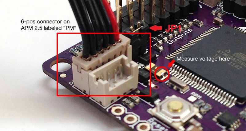
The 6-pos cable plugs into the 6-pos connector on both the Power Module and APM.
Your battery connects to the Power Module’s male connector, and its female connector plugs into your ESC or Power Distribution Board.
Note for ArduPlane users:
You must remove the APM’s JP1 jumper when using the Power Module so your electronics are only powered from the Power Module’s on board regulator and not from your ESC’s built in BEC.
Removing the jumper allows you to use the APM’s servo output rail to distribute power from your ESC’s BEC or separate UBEC to your servos.
Plug a BEC or UBEC power wire and ground wire into two of the power and ground pins on the APM’s servo output rail.
Note for ArduCopter users:
You should normally remove the APM’s JP1 jumper when using the Power Module so that only your APM board and your receiver are powered from the Power Module’s on-board regulator and not from your ESCs.
Removing the jumper allows you to use the APM’s servo output rail to distribute power from your ESC’s BEC or separate UBEC to any servos or external equipment.
If you are using servos, plug an ESC BEC or stand alone UBEC power wire and ground wire into two of the power and ground pins on the APM’s servo output rail to provide a common power and ground bus for servo power.
You can leave the jumper present if you are using ESCs that have no BECs or if all the ESC BECs power wires are cut and you are not powering any servos from the servo out rail.
You can also individually power each servo from each individual ESC-BEC.
Simply run the power and ground from each ESC-BEC individually and directly to each servo. (Very handy for multicopters).
Setup through mission planner
Battery measurement is set up in the Mission Planner’s Hardware > Optional Hardware > Battery Monitor screen
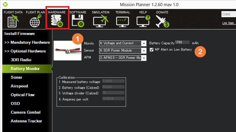
1 Enable voltage and current sensing by selecting:
Monitor: 4: Voltage and Current
Sensor: 4: 3DR Power Module
APM: 2: APM2.5 – 3DR Power Module
Battery Capacity: Fill in the your battery capacity in mAh
2 Low Battery Alert from ground station
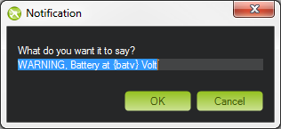
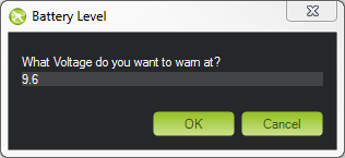
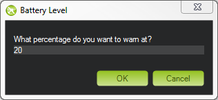
If you wish the mission planner to alert you verbally when your battery is low check the “MP Alert on Low Battery” checkbox and enter the warning you wish to hear (it will be read out by a computerized voice), the voltage level and finally the percentage of remaining current.
